On many types of equipment, the direction of motor rotation is critical. The direction of rotation of any three-phase motor can be changed by reversing 2 of its stator leads. This causes the direction of the turning electromagnetic field to reverse. When a motor is linked to a device that will not be damaged when its motor rotation is reversed, power can be momentarily applied to the motor to observe its direction of rotation. If the rotation is incorrect, any two line leads can be interchanged to reverse the motor’s rotation.
When a motor is to be linked to a machine that can be damaged by incorrect motor rotation, the direction of rotation must be figured out before the motor is linked to its load. The direction of motor rotation can be figured out in two standard ways. One means is to make an electric connection to the motor before it is mechanically connected to the load. The direction of rotation can then be tested by briefly putting power to the motor prior to it’s connection to the load.
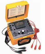
There could be occasions when it is not useful or is very bothersome to apply power to the motor before it is linked to the load. In such a case, a phase rotation meter can be utilized. The phase rotation meter compares the phase rotation of two various three-phase connections. The meter consists of six terminal leads. 3 of the leads are connected to one side of the meter and are labeled MOTOR. These 3 motor leads are identified A, B, or C. The LINE leads are found on the other side of the meter and are labeled A, B, or C.

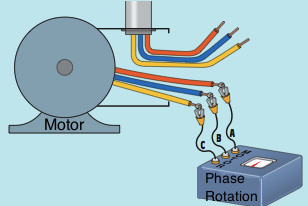
Phase Rotation Meter to the Load

Phase Rotation Meter
To determine the direction of motor rotation, first zero the meter by following the directions offered by the manufacturer. Then set the meter selector switch to MOTOR, and connect the three MOTOR leads of the meter to the “T” leads of the motor (Image above). The phase rotation meter contains a zero-center voltmeter. One side of the voltmeter is labeled INCORRECT, and the opposite is identified CORRECT. While observing the zero-center voltmeter, manually turn the motor shaft in the direction of preferred motor rotation. The zero-center voltmeter will immediately swing in the CORRECT or INCORRECT direction. When the motor shaft stops turning, the needle might swing in the opposite direction. It is the first indication of the voltmeter that is to be made use of.
If the voltmeter needle shows CORRECT, tag the motor T leads A, B, or C to correspond with the MOTOR leads from the stage rotation meter. If the voltmeter needle shows INCORRECT, alter any 2 of the MOTOR leads from the stage rotation meter and again turn the motor shaft. The voltmeter needle ought to now show CORRECT. The motor T leads can now be labeled to correspond with the MOTOR leads from the stage rotation meter.

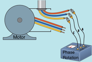
Phase rotation meter to the line
After the motor T leads have actually been identified A, B, or C to correspond with the leads of the phase rotation meter, the rotation of the line providing power to the motor must be figured out. Set the selector switch and turn on the phase rotation meter to the LINE position. After making sure the power has actually been shut off, link the three LINE leads of the stage rotation meter to the inbound cable (Picture above). Turn on the power and observe the zero-center voltmeter. If the meter is pointing in the CORRECT direction, switch off the power and label the line leads A, B, or C to correspond with the LINE leads of the phase rotation meter.
If the voltmeter is pointing in the INCORRECT direction, switch off the power and alter any both of the leads from the phase rotation meter. When the power is turned on, the voltmeter must point in the CORRECT direction. Turn off the power and tag the line leads A, B, or C to correspond with the leads from the stage rotation meter.
Now that the motor T leads and the incoming power leads have been labeled, connect the line lead labeled A to the T lead identified A, the line lead identified B to the T lead labeled B, and the line lead identified C to the T lead identified C. When power is linked to the motor, it will run in the appropriate motor rotation.
Check out our Facebook Page Here!

