Auto Transformer

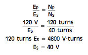
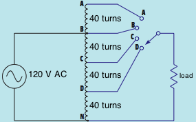
Auto transformers are one-winding transformers. They use the same winding for both the primary and secondary. The primary winding in the image below is between points B and N and has a voltage of 120 volts put on it. If the turns of wire are counted in between points B and N, it can be seen that there are 120 turns of wire. Now assume that the selector switch is set to point D. The load is now linked in between points D and N. The secondary of this transformer consists of 40 turns of wire. If the quantity of voltage put on the load is to be calculated, the following formula can be made use of:

Auto transformer Auto Transformer

Rotary Switch
Auto-transformers have only one winding for both the primary ans secondary


auto transformer formula Auto Transformer


 Auto transformer calculations

Presume that the load linked to the secondary has an impedance of 10 ohms. The amount of current flow in the secondary circuit can be computed making use of the formula:

auto transformer formulas Auto Transformer

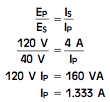
The primary current can be computed by using the same formula that was utilized to calculate primary current for an isolation sort of transformer:

primary current formula Auto Transformer

The quantity of power input and output for the auto transformer must coincide, just as they are in an isolation transformer:

primary current Auto Transformer

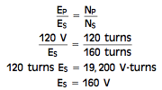
Now assume that the rotary switch is connected to point A. The load is now linked to 160 turns of wire. The voltage put on the load can be computed by:

auto transformer voltage Auto Transformer

Notice that the auto transformer, like the isolation transformer, can be either a step-up or step-down transformer.

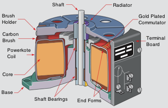
If the rotary switch revealed above were to be gotten rid of and replaced with a sliding tap that made contact straight to the transformer winding, the turns ratio could be adjusted continuously. This kind of transformer is commonly described as a Variac or Power-stat depending on the supplier. A cutaway view of a changeable auto transformer is revealed below. The windings are coiled around a tape-wound toroid center inside a plastic case. The tops of the windings have been milled flat to offer a commutator. A carbon brush makes contact with the windings.

inside auto transformer Auto Transformer

Auto transformers are often made use of by power companies to provide a little increase or decrease to the line voltage. They help offer voltage law to big power lines. The auto transformer does have one drawback. Because the load is connected to one side of the power line, there is no line isolation between the incoming power and the load. This can trigger problems with particular sorts of equipment and have to be a factor to consider when making a power system.

Check out our Facebook Page Here!
Single Phase Transformers

Transformers are among the most common devices discovered in the electric field. They vary in size from less than one cubic inch to the dimension of rail vehicles. Their ratings can easily vary from milli-volt-amperes (mVA) to giga-volt-amperes (GVA). It is crucial that anyone operating in the electric industry have an understanding of transformer types and connections. This article offers transformers intended for use in single phase installations (hence the term single phase transformers). There are 2 major sorts of single phase transformers, isolation transformers and auto-transformers.

A transformer is a magnetically run equipment that could alter values of voltage, current, and impedance without a change of regularity. Transformers are the most efficient machines known to man. Their effectiveness commonly range from 90 % to 99 % at complete load. Transformers can be broken down in to 3 categories:.

1. Isolation transformers
2. Auto-transformers
3. Current transformers

Values of a transformer are proportional to its turn ratio

All values of a transformer are equal to its turns proportion. This does not mean that the specific number of turns of wire on each winding need to be known to determine various worth’s of voltage and current for a transformer. Exactly what ought to be known is the proportion of turns. As an example, assume a transformer has 2 windings. One winding, the primary, has 1000 turns of wire; and the other, the secondary, has 250 turns of wire. The turns ratio of this transformer is 4 to 1, or 4:1 (1000 turns / 250 turns = 4). This indicates there are four turns of wire on the primary for every one turn of cable on the secondary.

Various formulas can be utilized to discover the values of voltage and current for a transformer. The following is a checklist of basic solutions.

Transformer Formulas

The primary winding of a transformer is the power input winding. It is the winding that is connected to the inbound power quantity. The secondary winding is the load winding, or output winding. It is the edge of the transformer that is connected to the forced load.


Isolation transformers

isolation transformer Single Phase Transformers

An isolation transformer has its primary and secondary windings electrically separated from each other.

Isolation transformers implies that the secondary winding is physically and electrically separated from the primary winding. There is no electric link in between the primary and secondary winding. This transformer is magnetically paired, not electrically coupled. This line isolation is frequently a very preferable feature. The isolation transformer greatly lowers any voltage spikes that originate on the quantity side before they are moved to the load edge. Some isolation transformers are built with a turns ratio of 1:1. A transformer of this type has the very same input and outcome voltages and is used for the purpose of isolation only.

transformer voltage spike Single Phase Transformers

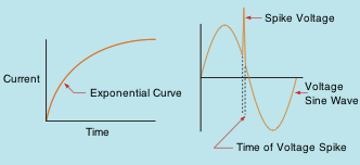
DC through an inductor. Short duration voltage spikes

The reason that isolation transformers can considerably reduce any sort of voltage increases prior to they hit the secondary is due to the rise time of current through an inductor. DC in an inductor increases at an exponential rate. As the current boosts in value, the broadening electromagnetic field cuts through the conductors of the coil and generates a voltage that is opposed to the used voltage. The quantity of induced voltage is symmetrical to the value of modification of current. This merely indicates that the faster current tries to increase, the higher the opposition to that rise is. Spike voltages and current flows are typically of really short duration, meaning that they enhance in value incredibly rapidly. This quick change of value induces the opposition to the change to increase just as swiftly. By the time the spike has actually been moved to the secondary winding of the transformer, it has actually been gotten rid of or substantially lessened.

Auto-transformers

Auto-transformers are one-winding transformers. They utilize the exact same winding for both the primary and secondary. The primary winding is in between stages B and N and has a voltage of 120 volts applied to it. If the turns of cable are counted between points B and N, it can be seen that there are 120 turns of wire. Now presume that the selector change is set to direct D. The load is now connected in between stages D and N. The secondary of this transformer contains 40 turns of cable.

Auto transformer Single Phase Transformers

Auto-transformers have only one winding for both the primary ans secondary

Check out our Facebook Page Here!
Plugin from the creators of Brindes Personalizados :: More at Plulz Wordpress Plugins