The Oscilloscope
Many of the electronic control systems in today’s industry produce voltage pulses that are meaningless to a VOM. In many instances, it is necessary to know not only the amount of voltage present at a particular point, but also the length or duration of the pulse and its frequency. Some pulses may be less than 1 volt and last for only a millisecond. A VOM would be useless for measuring such a pulse. It is therefore necessary to use an oscilloscope to learn what is actually happening in the circuit.
The oscilloscope is a powerful tool in the hands of a trained technician. The first thing to understand is that an oscilloscope is a voltmeter. It does not measure current, resistance, or watts. The oscilloscope measures an amount of voltage during a period of time and produces a two-dimensional image.
Voltage Range Selection
The oscilloscope is divided into two main sections. One section is the voltage section, and the other is the time base. The display of the oscilloscope is divided by vertical and horizontal lines. Voltage is measured on the vertical, or Y, axis of the display, and time is measured on the horizontal, or X, axis. When using a VOM, a range-selection switch is used to determine the full-scale value of the meter. Ranges of 600 volts, 300 volts, 60 volts, and 12 volts are common. The ability to change ranges permits more accurate measurements to be made.
Oscilloscopes can be divided into two main types: analog and digital. Analog oscilloscopes have been used for years and many are still in use; however,
(Voltage is measured on the vertical or Y axis and time is measured on the horizontal or X axis)
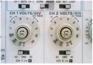
digital oscilloscopes are rapidly taking their place. Analog scopes generally employ some type of control knob to change their range of operation. The setting indicates the volts per division instead of volts full scale. The settings indicate that Channel 1 is set for 0.2 volts per division and Channel 2 is set for 0.5 volts per division.
(Voltage control of an analog oscilloscope.)
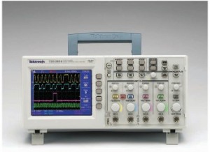
Digital oscilloscopes often indicate their setting on the display instead of marking them on the face of the oscilloscope. In the lower left-hand corner of the display the notation CH1 200mV can be seen. This indicates that the voltage range has been set for 200 millivolts per division.
Oscilloscopes can display both positive and negative voltages.
The Time Base
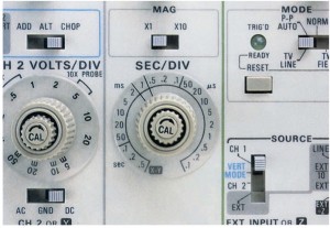
The next section of the oscilloscope to be discussed is the time base. The time base is calibrated in seconds per division and has ranges from seconds to microseconds. Analog type oscilloscopes use a range selection switch.
Measuring Frequency
Since the oscilloscope has the ability to display the voltage with respect to time, it is possible to compute the frequency of the waveform. The frequency (f ) of an AC waveform can be found by dividing 1 by the time (t) it takes to complete one cycle (f = 1/t). Many oscilloscopes have the ability to measure frequency automatically and dis- play the value for you.
Attenuated Probes
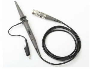
Most oscilloscopes use a probe that acts as an attenuator. An attenuator is a device that divides or makes smaller the input signal. An attenuated probe is used to permit higher voltage readings than are normally possible. For example, most attenuated probes are 10 to 1. This means that if the voltage range switch is set for 5 volts per division, the display would actually indicate 50 volts per division. If the voltage range switch is set for 2 volts per division, each division on the display actually has a value of 20 volts per division.
Probe attenuators are made in different styles by different manufacturers. On some probes, the attenuator is located in the probe head itself, while on others the attenuator is located at the scope input. Regardless of the type of attenuated probe used, it may have to be compensated or adjusted. In fact, probe compensation should be checked frequently. Different manufacturers use different methods for compensating their probes, so it is generally necessary to follow the procedures given in the operator’s manual for the probe being used.
Oscilloscope Controls
The following is a list of common controls found on the oscilloscope:
1. POWER. The power switch is used to turn the oscilloscope ON or OFF.
2. BEAM FINDER. This control is used to locate the position of the trace if it is off the display. The BEAM FINDER button will indicate the approximate location of the trace. The position controls are then used to move the trace back on the display.
3. PROBE ADJUST (sometimes called calibrate). This is a reference voltage point used when compensating the probe. Most probe adjust points produce a square wave signal of about 0.5 volts.
4. INTENSITY and FOCUS. The INTENSITY control adjusts the brightness of the trace. A bright spot should never be left on the display because it will burn a spot on the face of the cathode ray tube (CRT). This burned spot results in permanent damage to the CRT. The FOCUS control sharpens the image of the trace.
5. VERTICAL POSITION. This is used to adjust the trace up or down on the display. If a dual-trace oscilloscope is being used, there will be two vertical POSITION controls. (A dual-trace oscilloscope contains two separate traces that can be used separately or together.)
6. CH 1–BOTH–CH 2. This control determines which channel of a dual-trace oscilloscope is to be used, or if they are both to be used at the same time.
- ADD –ALT.– CHOP. This control is active only when both traces are being displayed at the same time. The ADD adds the two waves together. ALT. stands for alternate. This alternates the sweep between Channel 1 and Channel 2. The CHOP mode alternates several times during one sweep. This generally makes the display appear more stable. The CHOP mode is generally used when displaying two traces at the same time.
- AC–GND–DC.The AC is used to block any DC voltage when only the AC portion of the voltage is to be seen. For instance, assume an AC voltage of a few millivolts is riding on a DC voltage of several hundred volts. If the voltage range is set high enough so that 100 VDC can be seen on the display, the AC voltage cannot be seen. The AC section of this switch inserts a capacitor in series with the probe. The capacitor blocks the DC voltage and permits the AC voltage to pass. Since the 100 VDC has been blocked, the voltage range can be adjusted for millivolts per division, which will permit the AC signal to be seen.The GND section of the switch stands for ground. This section grounds the input so the sweep can be adjusted for 0 volt at any position on the display. The ground switch grounds at the scope and does not ground the probe. This permits the ground switch to be used when the probe is connected to a live circuit. The DC section permits the oscilloscope to display all of the voltage, both AC and DC, connected to the probe.
- HORIZONTAL POSITION. This control adjusts the position of the trace from left to right.
- AUTO–NORMAL. This determines whether the time base will be triggered automatically or operated in a free-running mode. If this control is operated in the NORM setting, the trigger signal is taken from the line to which the probe is connected. The scope is generally operated with the trigger set in the AUTO position.
- LEVEL. The LEVEL control determines the amplitude the signal must be before the scope triggers.
- SLOPE. The SLOPE permits selection as to whether the trace is triggered by a negative or positive waveform.
- INT.–LINE–EXT. The INT. stands for internal. The scope is generally operated in this mode. In this setting, the trigger signal is provided by the scope. In the LINE mode, the trigger signal is provided from a sample of the line. The EXT, or external, mode permits the trigger pulse to be applied from an external source.
Interpreting Waveforms
When using the oscilloscope, one must keep in mind that the display shows the voltage with respect to time. Learning to interpret the waveforms seen on the display of an oscilloscope will take time and practice, but it is well worth the effort. The oscilloscope is the only means by which many of the waveforms and voltages found in electronic circuits can be understood. Consequently, the oscilloscope is the single most valuable piece of equipment a technician can use.


