Isolation Transformers

Isolation transformers indicates that the secondary winding is physically and electrically isolated from the primary winding. There is no electric hookup between the primary and secondary winding. The transformer is magnetically combined, not electrically paired. The line isolation is frequently a very desirable attribute. Isolation transformers significantly minimizes any voltage increases that stem on the supply side, prior to they are moved to the load side. Some isolation transformers are built with a turns ratio of 1:1. A transformer of this type has the same input and output voltages and is used for the function of isolation only.

isolation transformer Isolation Transformers

An isolation transformer has its primary and secondary windings electrically separated from each other.

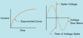
The reason that the isolation transformers can considerably reduce any voltage spikes prior to they reach the secondary is because of the grow time of current through an inductor. DC in an inductor increases at a rapid rate. As the current rises in value, the broadening magnetic field cuts through the conductors of the coil and causes a voltage that is opposed to the used voltage. The amount of induced voltage is proportional to the rate of change of current.

transformer voltage spike Isolation Transformers

DC through an inductor. Short duration voltage spikes

This simply implies that the much faster current tries to increase, the greater the opposition to that increase is. Spike voltages and currents are generally of very brief period, which means that they raise in value very quickly. This rapid modification of value triggers the opposition to the change to enhance just as quickly. By the time the spike has been transferred to the secondary winding of the transformer, it has been removed or greatly lowered.

Basic Operation of Isolation Transformers

isolation transformer magnetic Isolation Transformers

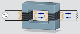
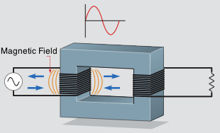
Isolation Transformer Magnetic Field

One winding of  an isolation transformer has been linked to an AC supply, and the various other winding has actually been connected to a load. As current boosts from absolutely nothing to its peak positive point, a magnetic field expands outward around the coil. When the current decreases from its peak positive point towards zero, the magnetic field collapses. When the current boosts towards its negative peak, the magnetic field once again broadens however with an opposite polarity of that previously. The area again breaks down when the current lowers from its negative peak toward zero. This continuously broadening and breaking down magnetic field cuts the windings of the primary and induces a voltage into it. This induced voltage opposes the used voltage and limits the current flow of the primary. When a coil induces a voltage into itself, it is called self-induction.

isolation transformer construction Isolation Transformers

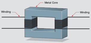
Construction of Isolation Transformer

The standard building of isolation transformers is revealed above. A metal center is made use of to provide great magnetic coupling between the two windings. The center is usually made of lamination’s stacked together. Laminating the center helps minimize power losses triggered by eddy current induction.

Excitation Current

There will always be some amount of current flow in the primary of any voltage transformer despite type or size even if there is no load linked to the secondary. This current flow is called the excitation current of the transformer. The excitation current is the quantity of current needed to allure the core of the transformer. The excitation current remains constant from no load to complete load. As a general rule, the excitation current is such a small part of the full load current that it is commonly left out when making computations.

Mutual Induction

Because the secondary windings of an isolation transformer are wound on the same core as the primary, the electromagnetic field produced by the primary winding also cuts the windings of the secondary. This continuously altering electromagnetic field causes a voltage into the secondary winding. The ability of one coil to cause a voltage into another coil is called shared induction. The amount of voltage caused in the secondary is identified by the ratio of the number of turns of wire in the secondary to those in the primary.

isolation transformer mutual induction Isolation Transformers

isolation transformer mutual induction

Multiple Tapped Windings

It is not uncommon for isolation transformers to be created with windings that have more than one set of lead wires connected to the primary or secondary. These are called multiple-tapped windings. The transformer revealed above includes a secondary winding rated at 24 volts. The primary winding consists of several taps, nevertheless. One of the primary lead wires is labeled C and is the typical for the various other leads. The other leads are labeled 120 volts, 208 volts, and 240 volts. This transformer is designed in such a manner that it can be linked to different primary voltages without altering the value of the secondary voltage. In this example, it is presumed that the secondary winding has a total amount of 120 turns of wire. To preserve the correct turns ratio, the primary would have 600 turns of wire in between C and 120 volts, 1040 turns between C and 208 volts, and 1200 turns between C and 240 volts.
Multiple Tapped Windings Isolation Transformers

Multiple Tapped Transformer Primary Winding

Single Phase Transformers

Transformers are among the most common devices discovered in the electric field. They vary in size from less than one cubic inch to the dimension of rail vehicles. Their ratings can easily vary from milli-volt-amperes (mVA) to giga-volt-amperes (GVA). It is crucial that anyone operating in the electric industry have an understanding of transformer types and connections. This article offers transformers intended for use in single phase installations (hence the term single phase transformers). There are 2 major sorts of single phase transformers, isolation transformers and auto-transformers.

A transformer is a magnetically run equipment that could alter values of voltage, current, and impedance without a change of regularity. Transformers are the most efficient machines known to man. Their effectiveness commonly range from 90 % to 99 % at complete load. Transformers can be broken down in to 3 categories:.

1. Isolation transformers
2. Auto-transformers
3. Current transformers

Values of a transformer are proportional to its turn ratio

All values of a transformer are equal to its turns proportion. This does not mean that the specific number of turns of wire on each winding need to be known to determine various worth’s of voltage and current for a transformer. Exactly what ought to be known is the proportion of turns. As an example, assume a transformer has 2 windings. One winding, the primary, has 1000 turns of wire; and the other, the secondary, has 250 turns of wire. The turns ratio of this transformer is 4 to 1, or 4:1 (1000 turns / 250 turns = 4). This indicates there are four turns of wire on the primary for every one turn of cable on the secondary.

Various formulas can be utilized to discover the values of voltage and current for a transformer. The following is a checklist of basic solutions.

Transformer Formulas

The primary winding of a transformer is the power input winding. It is the winding that is connected to the inbound power quantity. The secondary winding is the load winding, or output winding. It is the edge of the transformer that is connected to the forced load.


Isolation transformers

isolation transformer Single Phase Transformers

An isolation transformer has its primary and secondary windings electrically separated from each other.

Isolation transformers implies that the secondary winding is physically and electrically separated from the primary winding. There is no electric link in between the primary and secondary winding. This transformer is magnetically paired, not electrically coupled. This line isolation is frequently a very preferable feature. The isolation transformer greatly lowers any voltage spikes that originate on the quantity side before they are moved to the load edge. Some isolation transformers are built with a turns ratio of 1:1. A transformer of this type has the very same input and outcome voltages and is used for the purpose of isolation only.

transformer voltage spike Single Phase Transformers

DC through an inductor. Short duration voltage spikes

The reason that isolation transformers can considerably reduce any sort of voltage increases prior to they hit the secondary is due to the rise time of current through an inductor. DC in an inductor increases at an exponential rate. As the current boosts in value, the broadening electromagnetic field cuts through the conductors of the coil and generates a voltage that is opposed to the used voltage. The quantity of induced voltage is symmetrical to the value of modification of current. This merely indicates that the faster current tries to increase, the higher the opposition to that rise is. Spike voltages and current flows are typically of really short duration, meaning that they enhance in value incredibly rapidly. This quick change of value induces the opposition to the change to increase just as swiftly. By the time the spike has actually been moved to the secondary winding of the transformer, it has actually been gotten rid of or substantially lessened.

Auto-transformers

Auto-transformers are one-winding transformers. They utilize the exact same winding for both the primary and secondary. The primary winding is in between stages B and N and has a voltage of 120 volts applied to it. If the turns of cable are counted between points B and N, it can be seen that there are 120 turns of wire. Now presume that the selector change is set to direct D. The load is now connected in between stages D and N. The secondary of this transformer contains 40 turns of cable.

Auto transformer Single Phase Transformers

Auto-transformers have only one winding for both the primary ans secondary