The operating principle for all three-phase motors is the rotating magnetic field. There are 3 elements that trigger the magnetic field to turn. These are:
1. the fact that the voltages in a three-phase system are 120? out of phase with each other.
2. the fact that the three voltages alter polarity at routine intervals.
3. the arrangement of the stator windings around the inside of the motor.
3 phase operating principles and rotating magnetic field
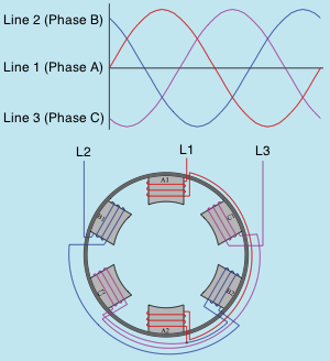
The image above shows 3 AC sine waves 120? out of phase with each other, and the stator winding of a three-phase motor. The stator illustrates a two-pole three phase motor. 2 pole implies that there are 2 poles per phase. AC motors do not normally have actual pole pieces like this image, but they will be utilized below to aid in comprehending how the rotating magnetic field is developed in a three-phase motor.
Notice that pole pieces A1 and A2 are found opposite each other. The exact same is true for poles B1 and B2 and C1 and C2. Pole pieces A1 and A2 are wound in such a manner that when current flows with the winding they will develop opposite magnetic polarities. This is likewise true for poles B1 and B2 and C1 and C2. The windings of poles B1 and C1 are wound in the exact same direction in relation to each other, but in opposite instructions from the winding of pole A1. The beginning end of the winding for poles A1 and A2 is connected to Line 1, the beginning end of the winding for poles B1 and B2 is linked to Line 2, and the beginning end of the winding for poles C1 and C2 is connected to Line 3. The finish ends of all three windings are joined to form a wye connection for the stator.
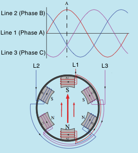
To understand exactly how the magnetic field turns around the inside of the stator (image above). A dashed line labeled A has been drawn with the 3 sine waves of the three-phase system. This line is utilized to show the condition of the 3 voltages at this point in time. The arrows drawn inside the motor indicate the greatest concentration of magnetic lines of flux; the arrows are pointing in the direction that shows magnetic lines of flux from north to south. Line 1 has actually reached its maximum peak voltage in the favorable direction and Lines 2 and 3 are less than maximum and in the adverse direction. The magnetic field is focused in between poles A1 and A2. Weaker lines of magnetic flux likewise exist in between poles B1 and B2 and C1 and C2. Also note that poles A1, B1, and C1 are all a south magnetic polarity. Poles A2, B2, and C2 form a north magnetic polarity.
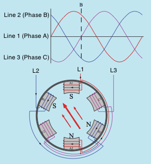
In the image above, line B is drawn at a time when the voltage of Line 3 is zero and the voltages of Lines 1 and 2 are less than optimum but opposite in polarity. The magnetic field is now concentrated in between the pole pieces of phases A and B. Phase C has no current flow at this time and therefore no electromagnetic field.
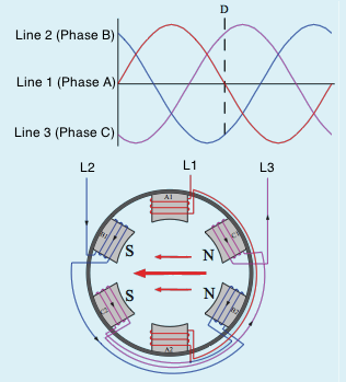
Line D indicates when Line 1 is zero and Lines 2 and 3 are less than max and opposite in polarity (image above). The electromagnetic field is now concentrated between the poles of stages B and C. At the end of one total cycle the magnetic field finishes a complete 360? of rotation. The speed of the turning magnetic field is 3600 rpm in a two-pole motor connected to a 60-Hz line.
Check out our Facebook Page!
Find outstanding oilfield equipment here: Oilfield & Gas Equipment for Sale Online
