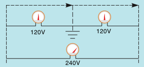
A typical type of isolation transformer is the distribution transformer. This kind of transformer changes the high voltage of power company distribution lines to the common 240/120 volts used to supply power to most homes and many buildings. In this example, it is presumed that the primary is linked to a 7200-volt line. The secondary is 240 volts with a center tap. The center tap is grounded and becomes the neutral conductor or common conductor. If voltage is measured around the whole secondary, a voltage of 240 volts is seen. If voltage is measured from either line to the center tap, half of the secondary voltage, or 120 volts, is seen (image below).
The reason this takes place is that the grounded neutral conductor becomes the center point of two out of phase voltages. If a vector diagram is drawn to show this condition, you will see that the grounded neutral conductor is linked to the center point of the two out of phase voltages (image below). Loads that are meant to operate on 240 volts, such as water heating systems, electric resistance heating rooms, and central air conditioning conditioners are connected directly throughout the lines of the secondary.
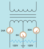
Loads that are meant to operate on 120 volts link from the center tap, or neutral, to among the secondary lines. The function of the neutral is to hold the distinction in current between the two secondary lines and keep a well balanced voltage.
?
?
?
?
?
?
In the image above, one of the secondary lines has a current flow of 30 amperes and the other has a current flow of 24 amperes. The neutral conducts the sum of the unbalanced load. In this instance, the neutral current is 6 amperes (30A - 24A = 6A).
Distribution Transformer Construction
A Distribution transformer is made the same way smaller sized transformers are made. Most utilize a ?C? or ?E? shaped core created from laminated sheet steel stacked and either glued together with a liquid bond or secured with steel straps. The low current, high voltage primaries are wound from enamel coated copper wire and the high current, low voltage secondaries are twisted using a thick bow of aluminum or copper insulated with resin twined paper. The whole assembly is done to heal the resin then dunked in a big powder coated steel tank. Next it is filled with high purity mineral oil, which is inert and non-conductive. The mineral oil helps eliminate heat and protects the transformer from dampness, which will stay on the surface of the oil. The storage tank is quickly depressurized to rid the transformer of any wetness that would cause arcing. A gasket is then placed on top to protect it from weather elements.


