Rotating Magnetic Field

The operating principle for all three-phase motors is the rotating magnetic field. There are 3 elements that trigger the magnetic field to turn. These are:

1. the fact that the voltages in a three-phase system are 120° out of phase with each other.
2. the fact that the three voltages alter polarity at routine intervals.
3. the arrangement of the stator windings around the inside of the motor.

3 phase operating principles and rotating magnetic field

rotating magnetic field Rotating Magnetic Field

3 phase stator and voltages

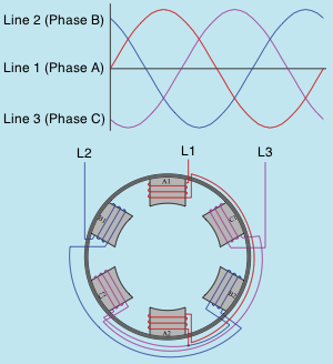
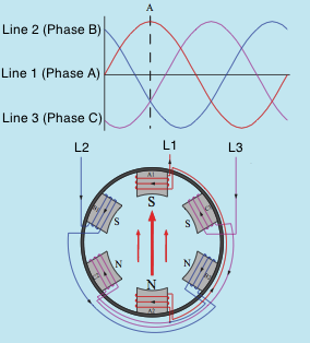
The image above shows 3 AC sine waves 120° out of phase with each other, and the stator winding of a three-phase motor. The stator illustrates a two-pole three phase motor. 2 pole implies that there are 2 poles per phase. AC motors do not normally have actual pole pieces like this image, but they will be utilized below to aid in comprehending how the rotating magnetic field is developed in a three-phase motor.

Notice that pole pieces A1 and A2 are found opposite each other. The exact same is true for poles B1 and B2 and C1 and C2. Pole pieces A1 and A2 are wound in such a manner that when current flows with the winding they will develop opposite magnetic polarities. This is likewise true for poles B1 and B2 and C1 and C2. The windings of poles B1 and C1 are wound in the exact same direction in relation to each other, but in opposite instructions from the winding of pole A1. The beginning end of the winding for poles A1 and A2 is connected to Line 1, the beginning end of the winding for poles B1 and B2 is linked to Line 2, and the beginning end of the winding for poles C1 and C2 is connected to Line 3. The finish ends of all three windings are joined to form a wye connection for the stator.

rotating magnetic field 2 Rotating Magnetic Field

magnetic field between poles A1 and A2

To understand exactly how the magnetic field turns around the inside of the stator (image above). A dashed line labeled A has been drawn with the 3 sine waves of the three-phase system. This line is utilized to show the condition of the 3 voltages at this point in time. The arrows drawn inside the motor indicate the greatest concentration of magnetic lines of flux; the arrows are pointing in the direction that shows magnetic lines of flux from north to south. Line 1 has actually reached its maximum peak voltage in the favorable direction and Lines 2 and 3 are less than maximum and in the adverse direction. The magnetic field is focused in between poles A1 and A2. Weaker lines of magnetic flux likewise exist in between poles B1 and B2 and C1 and C2. Also note that poles A1, B1, and C1 are all a south magnetic polarity. Poles A2, B2, and C2 form a north magnetic polarity.

rotating magnetic field 3 Rotating Magnetic Field

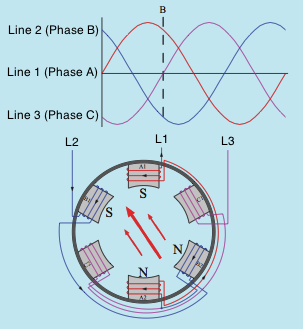
Magnetic field is between phases A and B

In the image above, line B is drawn at a time when the voltage of Line 3 is zero and the voltages of Lines 1 and 2 are less than optimum but opposite in polarity. The magnetic field is now concentrated in between the pole pieces of phases A and B. Phase C has no current flow at this time and therefore no electromagnetic field.

rotating magnetic field 4 Rotating Magnetic Field

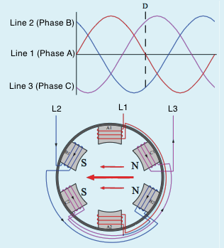
Magnetic field between phases B and C

Line D indicates when Line 1 is zero and Lines 2 and 3 are less than max and opposite in polarity (image above). The electromagnetic field is now concentrated between the poles of stages B and C. At the end of one total cycle the magnetic field finishes a complete 360° of rotation. The speed of the turning magnetic field is 3600 rpm in a two-pole motor connected to a 60-Hz line.
Transformer Core Types

There are many transformer core types used in the construction of transformers. A lot of cores are made from thin steel knock outs laminated together to form a solid metal core. Laminated cores are preferred because a thin layer of oxide forms on the area of each lamination and acts as an insulator to minimize the buildup of eddy currents inside the core material. The quantity of core material required for a specific transformer is determined by the power value of the transformer. The quantity of core product needed, must be met to prevent saturation at complete load. The type and form of the core normally determines the amount of magnetic coupling in between the windings and to some extent the performance of the transformer.


Transformer Core Types Transformer Core Types

Core-Type Transformer

Transformer core types

The transformer illustrated above is referred to as a core-type transformer. The windings are placed around each end of the center material. As a general guideline, the low-voltage winding is placed closest to the core and the high-voltage winding is put over the low-voltage winding.


Shell type transformer Transformer Core Types

Shell-type transformer

Shell-type transformer

The shell-type transformer is built in a similar manner to the core kind, except that the shell type has a metal core piece through the middle of the window (above). The primary and secondary windings are wound around the center core piece with the low-voltage winding being closest to the metal center. This plan permits the transformer to be bordered by the core and offers excellent magnetic coupling. When the transformer functions, all the magnetic flux needs to go through the center core piece. It then divides through the two external center pieces.


H type core transformer Transformer Core Types

H-type core transformer

H-type Core

The H-type core received (above) is similar to the shell-type core because it has an iron core through its center around which the primary and secondary windings are wound. The H core, nonetheless, surrounds the windings on 4 sides instead of two. This extra metal helps minimize stray leakage flux and enhances the efficiency of the transformer. The H-type center is commonly discovered on high-voltage distribution transformers.


toroid transformer Transformer Core Types

toroid transformer

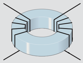
Tape-Wound Core

The tape-wound core or toroid core (above) is constructed by tightly winding one long constant silicon steel tape into a spiral. The tape might or could not be housed in a plastic container, relying on the application. This sort of center does not require steel knock outs laminated together. Because the center is one constant length of metal, flux leakage is kept to a minimum. Flux leakage is the amount of magnetic flux lines that do not follow the metal center and are lost to the bordering air. The tape-wound core is one of the most reliable core designs readily available.

Control Transformer

A typical kind of isolation transformer found throughout the electrical industry is the control transformer. The control transformer is used to reduce the line voltage to the value needed to operate control circuits. The most typical type of control transformer contains two primary windings and one secondary. The primary windings are generally valued at 240 volts each, and the secondary is valued at 120 volts. This arrangement provides a 2:1 turns ratio in between each of the primary windings and the secondary. For instance, presume that each of the primary windings contains 200 turns of wire. The secondary will consist of 100 turns of wire.

control transformer  Control Transformer

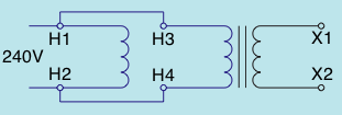
control transformer 240V AC

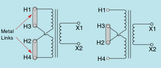
One the primary windings in the image above is identified H1 and H2. The other is identified H3 and H4. The secondary winding is designated X1 and X2. If the primary of the transformer is to be connected to 240 volts, the two primary windings are linked in parallel by connecting H1 and H3 together and H2 and H4 together. When the primary windings are linked in parallel, the same voltage is used around both windings. This has the exact same impact as making use of one primary winding with a total of 200 turns of wire. A turns ratio of 2:1 is maintained, and the secondary voltage is 120 volts.

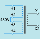
If the transformer is to be connected to 480 volts, the two primary windings are linked in series by connecting H2 and H3 together (shown below #2). The inbound power is linked to H1 and H4. When connecting the primary windings in series it has the effect of raising the number of turns in the primary to 400. This produces a turns ratio of 4:1. When 480 volts are connected to the primary, the secondary voltage will continue to be at 120.

control transformer links Control Transformer

240V and 480V hookups


control transformer 480v Control Transformer
control transformer 480v


The primary leads of a control transformer are usually cross-connected. This is done so that metal links can be made use of to link the primary for 240 volts or 480 volt operation. If the primary is to be linked for 240-volt operation, the metal links will be linked under screws. Notice that leads H1 and H3 are linked together and leads H2 and H4 are linked together. Contrast this hookup with the previous connection.
If the transformer is to be linked for 480-volt operation, terminals H2 and H3 are to be linked as shown above. Contrast this link with the hookup previously imaged.

Distribution Transformer

A typical type of isolation transformer is the distribution transformer. This kind of transformer changes the high voltage of power company distribution lines to the common 240/120 volts used to supply power to most homes and many buildings. In this example, it is presumed that the primary is linked to a 7200-volt line. The secondary is 240 volts with a center tap. The center tap is grounded and becomes the neutral conductor or common conductor. If voltage is measured around the whole secondary, a voltage of 240 volts is seen. If voltage is measured from either line to the center tap, half of the secondary voltage, or 120 volts, is seen (image below).

transformer values

The reason this takes place is that the grounded neutral conductor becomes the center point of two out of phase voltages. If a vector diagram is drawn to show this condition, you will see that the grounded neutral conductor is linked to the center point of the two out of phase voltages (image below). Loads that are meant to operate on 240 volts, such as water heating systems, electric resistance heating rooms, and central air conditioning conditioners are connected directly throughout the lines of the secondary.
Loads that are meant to operate on 120 volts link from the center tap, or neutral, to among the secondary lines. The function of the neutral is to hold the distinction in current between the two secondary lines and keep a well balanced voltage.

Voltages are out of phase

distribution transformer neutral Distribution Transformer

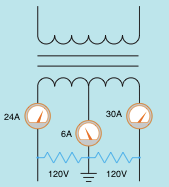
The neutral carries the unbalanced load


In the image above, one of the secondary lines has a current flow of 30 amperes and the other has a current flow of 24 amperes. The neutral conducts the sum of the unbalanced load. In this instance, the neutral current is 6 amperes (30A - 24A = 6A).

Distribution Transformer Construction

A Distribution transformer is made the same way smaller sized transformers are made. Most utilize a “C” or “E” shaped core created from laminated sheet steel stacked and either glued together with a liquid bond or secured with steel straps. The low current, high voltage primaries are wound from enamel coated copper wire and the high current, low voltage secondaries are twisted using a thick bow of aluminum or copper insulated with resin twined paper. The whole assembly is done to heal the resin then dunked in a big powder coated steel tank. Next it is filled with high purity mineral oil, which is inert and non-conductive. The mineral oil helps eliminate heat and protects the transformer from dampness, which will stay on the surface of the oil. The storage tank is quickly depressurized to rid the transformer of any wetness that would cause arcing. A gasket is then placed on top to protect it from weather elements.