A typical kind of isolation transformer found throughout the electrical industry is the control transformer. The control transformer is used to reduce the line voltage to the value needed to operate control circuits. The most typical type of control transformer contains two primary windings and one secondary. The primary windings are generally valued at 240 volts each, and the secondary is valued at 120 volts. This arrangement provides a 2:1 turns ratio in between each of the primary windings and the secondary. For instance, presume that each of the primary windings contains 200 turns of wire. The secondary will consist of 100 turns of wire.
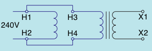
One the primary windings in the image above is identified H1 and H2. The other is identified H3 and H4. The secondary winding is designated X1 and X2. If the primary of the transformer is to be connected to 240 volts, the two primary windings are linked in parallel by connecting H1 and H3 together and H2 and H4 together. When the primary windings are linked in parallel, the same voltage is used around both windings. This has the exact same impact as making use of one primary winding with a total of 200 turns of wire. A turns ratio of 2:1 is maintained, and the secondary voltage is 120 volts.
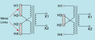
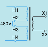
If the transformer is to be connected to 480 volts, the two primary windings are linked in series by connecting H2 and H3 together (shown below #2). The inbound power is linked to H1 and H4. When connecting the primary windings in series it has the effect of raising the number of turns in the primary to 400. This produces a turns ratio of 4:1. When 480 volts are connected to the primary, the secondary voltage will continue to be at 120.
?
?
?
?
?
?
?
?
The primary leads of a control transformer are usually cross-connected. This is done so that metal links can be made use of to link the primary for 240 volts or 480 volt operation. If the primary is to be linked for 240-volt operation, the metal links will be linked under screws. Notice that leads H1 and H3 are linked together and leads H2 and H4 are linked together. Contrast this hookup with the previous connection.
If the transformer is to be linked for 480-volt operation, terminals H2 and H3 are to be linked as shown above. Contrast this link with the hookup previously imaged.


